
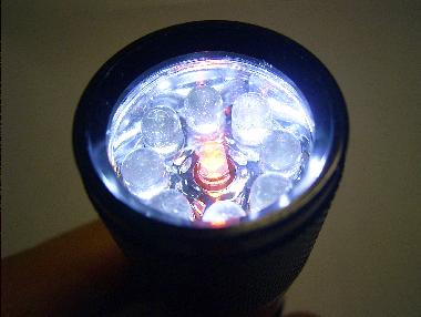
The boxed version of openSUSE 11.1 comes bundled with a LED-flashlight. Nice black and sturdy aluminum, Modern design with 9 white LEDs, no old-fashioned bulb that would produce more heat than illumination. Not flimsy, not heavy, just practical and quite bright. Batteries included. Exactly what I like.
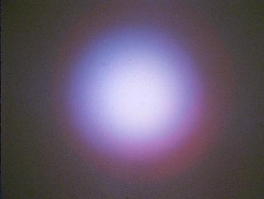
But alas, this high-tech-toy is not perfect. The LEDs produce a strange unnatural light, which makes people look really sick. It gives a bluish-greenish tint to everything. This I don’t like. Okay, it is state of the art with regard to white LEDs, so this is no real reason to complain. Still, it leaves room for improvement.
Let us adjust the color of the light, so that objects look more natural. This posting explains you how to do it in 3 easy (or 4 not so easy) steps.
1 Disassembly
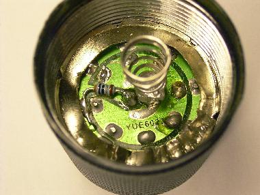
Unscrew the flashlight at the front end. Looking into the cap, you see a
printed circuit board (PCB) tucked down by a metal sheet ring.
I used a pair of good and pointed pliers to bite a notch in the ring to make it collapse. Then it can be pulled out easily. The PCB follows.
2 Reverse engineering
(This is the not so easy step. You can skip it. Step 3 will tell you right away
what you need.)
Inspecting the PCB, I find no resistors there, all LEDs are in parallel and are directly connect to the switch and battery pack. The battery pack provides 3×1.5 = 4.5 Volts — this is a bit too much for any LEDs. Blue and white ones have higheer voltages than other colors, but no datasheet I find for reference goes beyond 3.1V for white or 3.4V for blue. An Ohmmeter tells us, that the push-button switch at the back is only a switch, no resistors there. To see
what is really going on, we remove one of the LEDs, and solder a short length of thin two-wire cable in its place.
We also solder a 1cm piece of flexible wire onto one of the outer pads of the PCB to make contact with the housing. With this, we can reassemble the flashlight without metal ring and front glass, pulling the wires through the now vacant opening in the reflector.
Switching on, we can measure 3.5V at the wires. So all the LEDs in parallel are strong enough to pull down the voltage to an almost sane value, exploiting the internal resistance of those cheap AAA cells. Good.
I test one of my own white LEDs at the wires. It draws 35mA, which is above the nominal 20mA, but it seems to survive. Good. It is definitly brighter than the original LED, which only drew 18mA. Mine also has a larger viewing angle.
With this information, we can estimate that the original LEDs are rated ca. 2000-3000mcd, 3.3V, 15mA, and have ca. 12° viewing angle.
Now let us try to mix a more natural white.
A true white light radiates throughout the entire color spectrum. The human eye can adapt quite well to variations here. Covering a wide spectrum is important. Covering it evenly and without gaps is not.
For judging color quality, I collected a few photos, paintings, magazines, books and several other colorful objects and a white sheet of paper on my desk. You may use different objects. The idea is to compare colors under several lighting conditions. First we study colors in daylight, then with artificial light, and finally with an old fashioned flashlight (with a light bulb).
Now we test our flashlight and several different LEDs. We hold each LED in
parallel to the flashlight, and illuminate the objects and the piece of paper. Covering the exta LED with a finger is a fast way to see what kind of difference we may get.
The original impression was blue-ish. So let us start with yellow, the complementary color of blue.
First, we solder a yellow LED 10000mcd with an estimated 100 Ohm resistor to the wires. In my case it was not much effect. Doing some math, we find that we can risk a 47 Ohm resistor. Better, but red objects are still much to dark.
Next we test a red LED 12000mcd with 47 Ohm. Its viewing angle is wider and
the red was too strong for me. Back to 100 Ohm. Colors are quite good, but everything has a pink-ish touch, when compared to artificial light.
Finally, we try an orange LED 8000mcd with 47 Ohm. that looks quite good to me. Your results may vary, depending on the exact type of LEDs you are using.
This LED has a nominal voltage of 2.0V and current of 20mA, so the nominal resistor value should be (3.5V-2.0V)*0.020mA = 75 Ohm. Okay, It survived with 45 Ohms already, so we can try to lower the value a bit more (if we have one to spare). Let us try 30 Ohm for 5 minutes.
It survives and does not get too hot. The colors are quite nice, although the beam has an orange halo due to the wider viewing angle of the new LED.
We can cure this by replacing one (or a few) of the other LEDs with stronger white LEDs with the same 20° viewing angle as the orange LED has.
I also noted that shadows had green and orange edges, as I was holding my orange LED next to the white LEDs. To avoid these colorful shadows, we should place the orange LED in the center of the others. To reduce the halo, we apply at least one new white LED.
Now we have a plan.
3 Modding
Goal:
Have blue counteracted by sufficient orange. We may not get a perfectly balanced white but that does not matter.
Material:
- One orange LED 4000-8000mcd, 20° viewing angle. 600-610nm, 2.0V (e.g. Art Nr. 15601 or 13601 from www.leds.de)
- A small 30 Ohm resistor, smd-version if you dare.
- Optionally one (or more) white LED(s) ca 7000mcd, 20° viewing angle, 3.1V (e.g. Art Nr. 15005 from www.leds.de)
All in all ca. 0.50 EUR. (Or ca. 2 EUR if you want to replace all white LEDs too.)
Procedure:
- Remove the spring from the center pin by heating it with a soldering iron.
- Remove the center LED by heating both pins.
- Use a pointed knive to cut a gap into the circuit path leading from edge to center. Do not cut into your fingers. (Yes they are softer than the copper, but still, don’t do that.)
- Solder the 30 Ohm resistor across the gap. (Again, solder the copper, not your fingers, even if they have cuts by now.)
- Replace the center LED with the orange LED. The flat side (shorter wire) faces towards the resistor.
- Optionally replace some of the other LEDs bright white LEDs. The flat side
(shorter wire) faces outwards. - Solder the spring back in place, make sure it does not touch the other center LED pin, where the resistor is.
4 Re-Assembly
Take out the plastic glass from the cap, clean it. Put it back.
Fit the plastic reflector over the LEDs, this assembly into the cap.
Bring the metal ring back into shape. Maybe repair the ring by soldering.
Ideally, it snaps into the threading and can be screwed downwards.
If not, push it down onto the PCB using a screwdriver.
The ring should hold the PCB tight, we need good electrical contact
between the PCB and the housing.
Test your flashlight.
Was it worth it?
Both comments and pings are currently closed.
I guess a piece of CTO gelatin would have done the trick :
http://en.wikipedia.org/wiki/Color_correction
Less soldering, less geeky indeed…
I’d be interested to see if color gels really could do that, without filtering away too much of the light. We want to be efficient, with regard to energy saving, don’t we? 🙂